Among those who know me well, it’s likely no surprise that there are two things I really enjoy – solving problems and doing math. So, when I find a problem that turns out to be just a math problem, solving it is really fun. That’s what I did this weekend – I wanted to 3d print an addition to my 3d printer that would help my filament buffering problem, but the design required that I obey some obviously mathematical constraints.
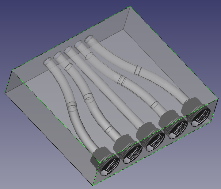
The core concept of my design is below – notably, I’m trying to build a filament path into a vertical buffer (repurposed Prusa MMU2S buffer, actually) and back out again using PTFE tubing and easy connectors. The only wrinkle is that the easy connectors require more spacing than the Prusa buffer had, so my connector box would have to tighten the spacing between them.
My quick design sketch then, looked like this:
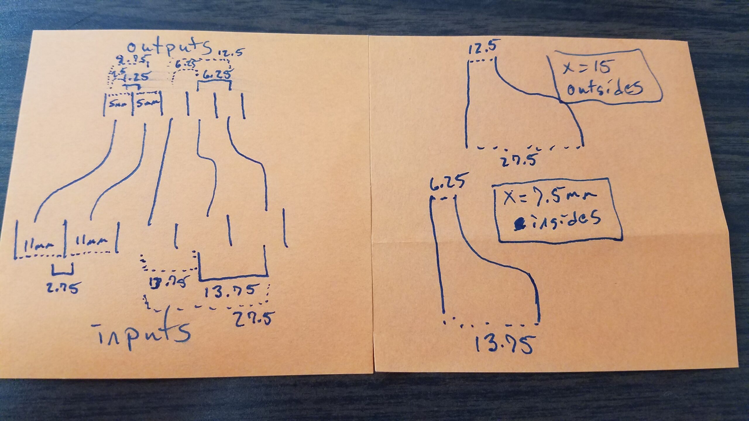
(yes, I do most of my designs/math on sticky notes first)
The main constraint here is the minimum bend radius of the PTFE tubing – the turns in the filament path shouldn’t violate that. So, if I avoided violating that constraint, how much of the circle should I use and how long would the box have to be? This is the math problem I was talking about. Phrased mathematically, that looked like:
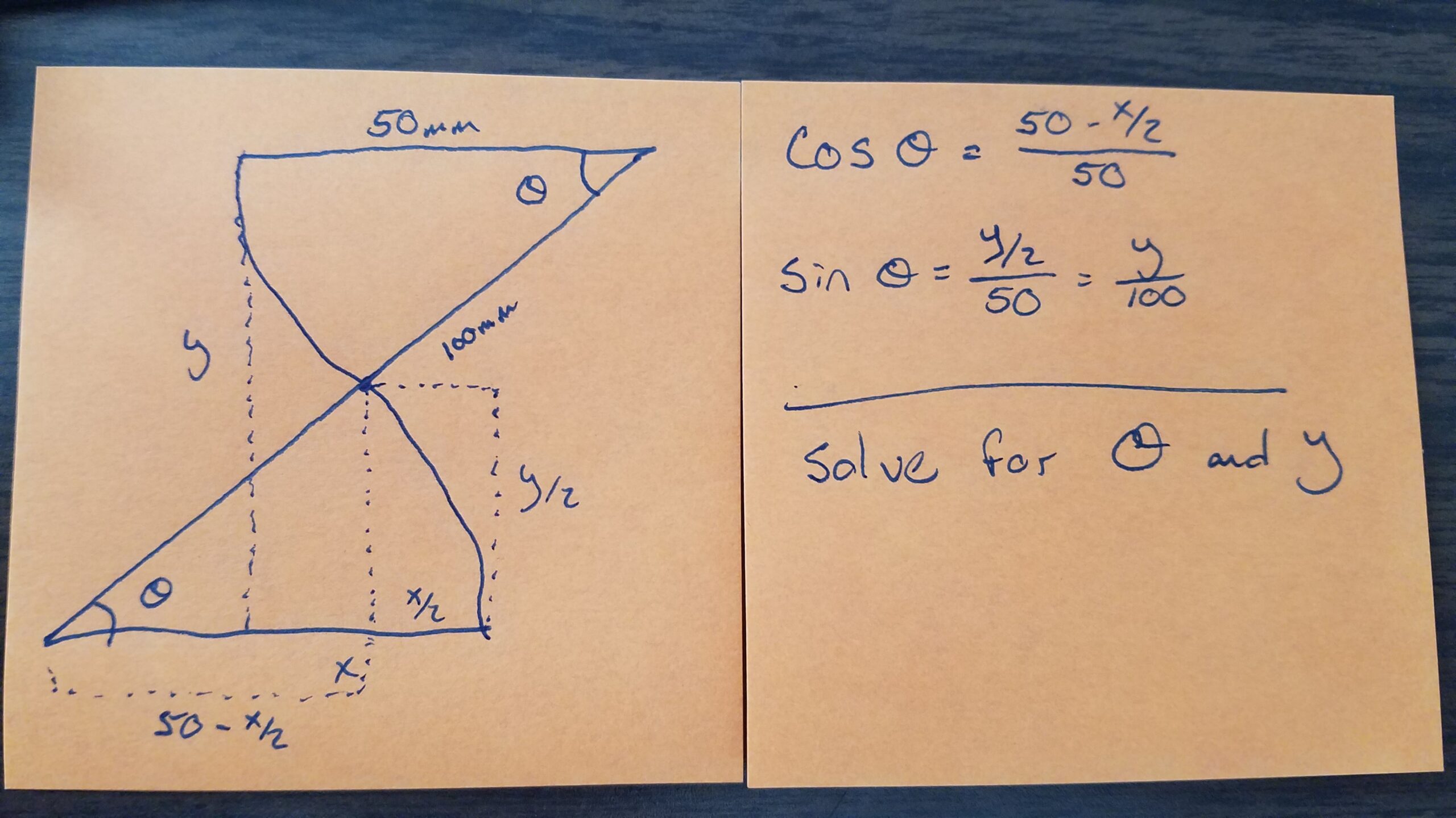
Where θ is the interior angle of the arc of the circle (and hence the arc of the torus I would use), X is the distance I needed to cover, and Y is the unknown amount of space I would need to have to cover the distance X without violating the minimum bend radius. I basically needed to solve this twice – once for the outer pair of tubes (which have a larger X since it is compressed further in) and once for the inner pair of tubes.
A quick google search and I found that the minimum bend radius of 4mm od/2mm id PTFE tubing (such that there would be no degradation/collapse of the tubing) was 40mm. I set my tolerances at 50mm just to be safe (and since space wasn’t such a concern, I just needed it to be greater than the minimum), and was off to solving. A bit of algebra and trigonometry later, and I got:
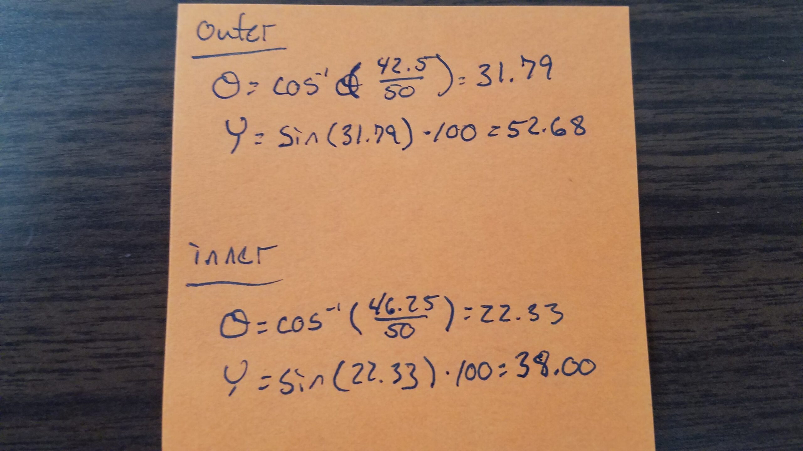
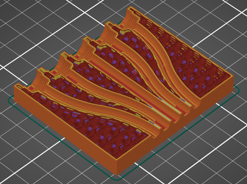
I was able to build this in FreeCAD with two partial torii per path (one to turn inward and one to straighten it back outward). And when I printed it, man was it smooth. Success!